Опыт эффективного изменения параметров проходки по данным автоматизированных гидростатических нивелиров с целью минимизации влияния на действующее сооружение Московского метрополитена (из опыта организации)
- цикличность измерений – данные с датчиков поступают 1 раз в минуту;
- независимость результатов измерений от погодных условий;
- отсутствие необходимости прямой видимости между датчиками;
- фиксированная точность измерений 0,1 мм, не зависящая от расстояния между датчиками и их количества.
Указанная цикличность наблюдений особенно актуальна при строительстве тоннелей, когда скорость проходки составляет около 250 м/мес. или 8,3 м/сутки. В то же время, постоянный контроль деформаций объектов мониторинга при этом позволяет оперативно изменять параметры проходки, обеспечивая сохранность существующих сооружений.
Кроме того, система обладает возможностью самодиагностики на предмет повреждения в процессе эксплуатации, а интернет-сервис позволяет настроить автоматическое формирование и рассылку уполномоченным лицам отчетов, информирование посредством смс-оповещений о достижении предельных деформаций.
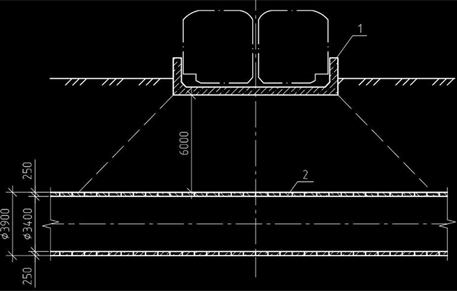
Учитывая все преимущества, указанные выше, система гидростатического нивелирования «Монитрон» была применена при закрытой проходке коллекторного тоннеля под действующим участком Московского метрополитена (см. рис. 2) между станциями «Филатов луг» и «Саларьево» Сокольнической линии. Проектируемый тоннель имеет наружный и внутренний диаметры 3,9 м и 3,4 м, соответственно.
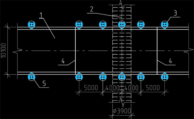
Проходка ведется ТПМК «Lovat RME-158 SE» (диаметр резанья 4,05 м) с активным грунтопригрузом забоя. Обделка тоннеля сборная железобетонная с последующим усилением под лотком метрополитена. Ширина кольца 750 мм. Каждое кольцо состоит из 6 трапециевидных блоков, в центре которых расположены отверстия для нагнетания раствора и заполнения строительного зазора. Протяженность тоннеля в технической зоне метрополитена составляет 50 м. Фактическая скорость проходки составляла 5.6 м/сутки. Расстояние в свету от обделки строящегося коллектора до сооружений метрополитена составляет 6,0 м (см. рис. 3).
Учитывая, что фактические деформации при проходке могут отличаться от проектных, целесообразно на стадии строительства иметь цифровой двойник (ЦД) сооружений, представляющий собой достаточно подробную МКЭ-модель проектируемого сооружения, вмещающего массива и существующих сооружений. Благодаря расчету ЦД с использованием заданных перемещений по данным гидростатических нивелиров появляется возможность оценить реальные запасы прочности конструкции и прогнозировать дальнейшее изменение напряженно-деформированного состояния как сооружений, так и основания.
В рассматриваемом случае, в ПВК ZSoil (см. рис. 4), был создан цифровой двойник, откалиброванный под проектные данные максимальной осадки. Это позволило до начала проходки назначить для каждого из датчиков гидростатического нивелирования предполагаемые графики зависимости осадки от положения ТПМК с границами прогнозного коридора (см. 1 на рис. 5), учитывающими точность геотехнических расчетов. Выход фактического графика осадки из прогнозного коридора может считаться сигналом к необходимости корректировки параметров проходки или применению защитных мероприятий.
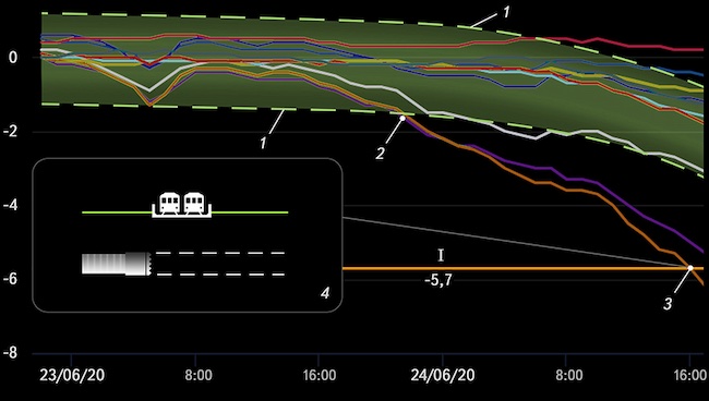
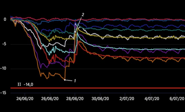
В соответствии с проектной документацией, в части оценки влияния строительства, выполненной сторонней организацией, были назначены расчетная осадка в 5,4 мм и предельно допустимая осадка в 14,0 мм, которые были использованы в сервисе https://monitron.xyz как значения (см. I на рис. 5, I и II на рис. 6), в процентном соотношении от которых происходит автоматическая рассылка смс-сообщений и электронных писем всем ответственным и заинтересованным лицам (например, инженер получит первое оповещение при 60% от расчетного значения, а его руководитель − при 80%).

Так, при проходке коллектора результаты мониторинга высотного положения действующего участка метрополитена 23/06/2020 в 22:00 показали, что его осадки достигли границ расчетного коридора цифрового двойника (см. точку 2 на рис. 5), что стало первым тревожным сигналом о необходимости внесения изменений в параметры проходки. При достижении проектной осадки в 5,7 мм (см. точку 3 на рис. 5) ООО «Научно-инженерный центр Тоннельной Ассоциации», осуществлявший научное сопровождение проходки, направил письмо с указанием о необходимости увеличения давления грунтопригруза до 0,6 бар, и корректировки срока схватывания тампонажного состава до 3-х часов.
Дальнейшая проходка, продолжавшаяся до 4:00 25/06/2020, показала недостаточность принятых мер, и при осадке в 10,7 мм (см. точку 1 на рис. 6 и рисунок 7), было направило второе письмо с указанием о необходимости увеличения давления грунтопригруза до 1,0 бар. Как показала дальнейшая проходка, эта мера также оказалась временной (см. рис. 6).
Уже к 12:00 26/06/2020 возник выраженный тренд нарастания осадки, которая к 4:00 27/07/2020 имела максимальное значение в 12,4 мм (см. точку 2 на рис. 6), что соответствует 87% от предельного значения, установленного эксплуатирующей организацией. Учитывая это, было принято решение выполнить работы по управляемому компенсационному нагнетанию [6-7] из строящегося тоннеля в основание действующего участка метрополитена. Суть работ заключалась в нагнетании растворов в каждое четное кольцо через отверстия в блоках обделки (рис. 8), до отказа по давлению в 4 бар.

Созданы реальные, проверенные на практике, предпосылки для комплексного геотехнического мониторинга на основе современных автоматизированных гидростатических нивелиров «Монитрон» и программного обеспечения по созданию цифровых двойников, обеспечивающие в совокупности постоянные наблюдения и контроль за изменением НДС строящихся или эксплуатируемых зданий и сооружений при освоении подземного пространства.
При анализе данных геотехнического мониторинга необходимо сопоставлять результаты измерений не с их расчетным максимальным значением, а с расчетными значениями деформаций по каждой точке наблюдений с учетом текущего этапа строительства, что позволяет сделать совместное применение автоматизированных гидростатических нивелиров «Монитрон» и цифрового двойника объекта мониторинга.
[1] Pellissier P F 1965 Hydrostatic leveling systems IEEE Transactions on Nuclear Science 1219–20
[2] Meier E, Geiger A, Ingensand H, Licht H, Limpach P, Steiger A and Zwyssig R 2010 Hydrostatic Levelling System: measuring at the system limits J. of App. Geodesy 4 91
[3] Tsvetkov R V, Yepin V V and Shestakov A P 2017 Numerical estimation of various influence factors on a multipoint hydrostatic leveling system IOP Conf. Ser. Materials Science and Engineering 208 012046
[4] Pospíšil J and Dandoš R 2018 Basic principles of hydrostatic levelling GeoScience Engineering64 12–21
[5] Zhang X, Zhang Y, Zhang L, Qiu G and Wei D 2018 Power transmission tower monitoring with hydrostatic leveling system: measurement refinement and performance evaluation Hindawi Journal of Sensors 2018 1–12
[6] Zertsalov M G, Simutin A N and Aleksandrov A V 2019 Calculated substantiation of controlled compensation grouting for lifting the foundation slab of Zagorsk PSP-2 Power Technology and Engineering 52 512–16
[7] Bellendir E N, Aleksandrov A V, Zertsalov M G and Simutin A N 2016 Building and structure protection and leveling using compensation grouting technology Power Technology and Engineering 50 142–6